|
 |
|
Αεροπορική Βιομηχανία
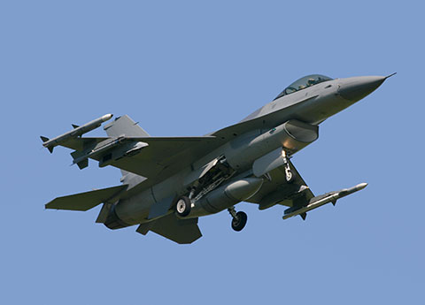
Τόσο η πολεμική όσο και η πολιτική αεροπορία εφαρμόζουν πλήθος δοκιμών, με σκοπό να εξασφαλίσουν το αξιόμαχο των αεροσκαφών και να προλάβουν βλάβες που θα μπορούσαν να έχουν ολέθρια αποτελέσματα τόσο για τα αεροσκάφη όσο και για τους επιβάτες ή τα πληρώματα τους.
Μερικές από τις πιο απαιτητικές εφαρμογές Μ.Κ.Ε. στην αεροπορική βιομηχανία παρουσιάζονται παρακάτω:
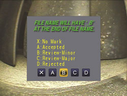
Automatic Fastener Hole Inspection in Aircraft
Damage Issue
The particular application to be solved with the AFIS was cracking at the Countersink and Faying surfaces in particular areas on the aluminum skin of the aircraft known to have these issues. Both aircraft suffered similar issues, with a main difference being that one aircraft had flush fastener heads and the other raised head and flush fastener types. Areas to be inspected were on the lower wing skin so access is from below the aircraft wing with minimal removal of components and limited spacing between fasteners.
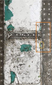
Detail of Inspection Areas (side)
Conventional Methods of Inspection
Traditionally the inspection was done with a conventional single beam water filled shoe system that was manually spun by the operator. In order to project the single beam into the area of interest the system would have to be mechanically adjusted very finely for each area and 2 scans (clockwise and counter clockwise) were performed with each adjustment to be able to detect cracks at any orientation. This was time consuming as there was only one beam and adjustment was critical. Additional concerns included, no data storage, harder to get replacement parts, and repeatability.
Conventional Ultrasonic Scanner
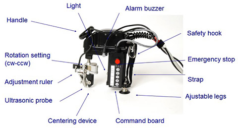
AFIS System
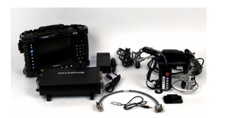
The AFIS system was developed with the following main components:
- OmniScan acquisition unit
- Motor Controller
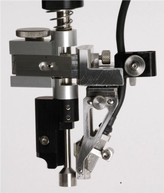
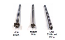
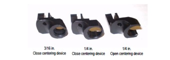
- Automated Scanner with applicable centering device (raised head or Phillips style)
- 16 element Phased Array Probe(s) and Wedge(s) designed to be able to scan around the needed area
- Calibration plate with representable notches and fastener types

AFIS Operation
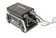
The AFIS system is able to project a sweep of beams at each interface simultaneously as shown below in a single scan. A centering device ensures proper probe spacing from the fastener center and the probe is scanned 360 + degrees around the fastener with a single button push. After the inspection the device automatically sets itself back into the home position for the next fastener. Almost all operation can be completed from the scanner interface including interval jogging, saving files, freezing the acquisition, homing, etc. Mechanical settings on the scanner allow for proper probe orientation for both CC/CCW scanning around the fastener. Only a fine mist of water based couplant is necessary and no paint removal is necessary. All different skin thicknesses are configured for on the calibration block, saved, and recalled for quick inspection from one fastener area to the next. Each area is typically viewed on the unit with an amplitude based S-Scan and C-Scan of the inspection. Low weight (around 2- 3 lbs. depending on configuration) was important as the unit must be used frequently and in an “above head” position. A light was added for low light conditions under the aircraft. All components can be housed in a single pelican case for easy transport and shipping. The past systems were designed to detect a .03-.05” notch at each surface per the requirements of the historical inspection but alternative sensitivities could be obtained.
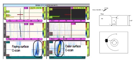
Detail of Scan and Representable Instrument Layout
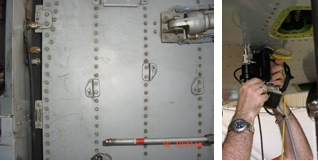
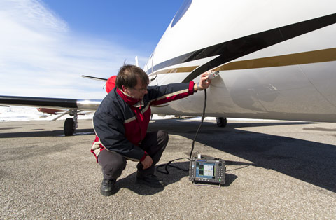
Detail of Typical Inspection Area and Applying AFIS scanner
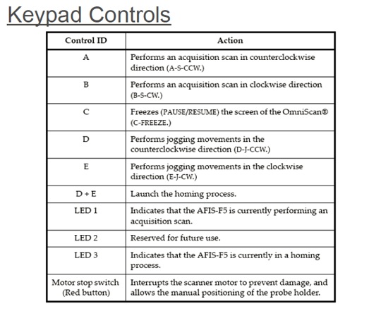
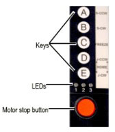
Example Commands from Keypad
Benefits of AFIS System
- Simultaneous inspection of faying and Countersink surfaces with a multitude of angles
- Automated scanning and full data retention
- Improved probability of detection with Phased Array Imaging and multiple angles
- Easy use with “at hand” control of most system commands via keypad on scanner
- Ergonomic light weight scanner with right and left handed keypad positions and multiple holding positions to lessen fatigue.
- Ruggedized for daily use in real world inspection scenarios under aircraft
- OmniScan based platform so system can be used for other inspections (UT/PA/EC/BT). (MX or MX2 possibilities depending on needs)
- Easy adjustment to varying skin thickness, fastener types and other inspection variables -(*Current tested thickness range approximately .180” to .660” and fastener diameters of 5/32”, 3/16”, 1/4”, and 5/16”. Current versions can accommodate both Phillips head and raised head fasteners).
- Adaption possible with portable flexible digital system (Heads up display glasses, Conventional UT spinning device for hard to reach areas, lateral sweeping configuration for hard to detect crack types, etc.)
- All analysis can be done directly on unit or in post analysis software. Digital alarming is also possible.
- Quick calibration verifications and adjustments
Conclusion
Olympus has developed and implimented a novel automated phased array system suitable for aircraft fastener hole inspection for 2 styles of military aircraft. It offers many benefits and is built around a flexible and portable concept which could be adapted to other aircraft fastener types and skin materials. Basing the system on the popular OmniScan acquisition unit allows flexibility to use the system for other ultrasonic and other NDT methods (MX based system offers modularity for EC/ECA/Bond Testing).
Note: The Scanning System detailed above have been designed with specific applications variables in mind.
Aircraft around the globe are repeatedly subjected to drastic temperature changes, which cause condensation and humidity to collect on the inside of the aluminum skin. This humid environment between layers leads to hidden corrosion that must be detected and repaired during regular in-service inspections.
As a part of its series of aerospace solutions, Olympus proposes an innovative fastener and subsurface corrosion inspection technique, which propels eddy current technology into previously uncharted territory. This new technology detects, sizes, and evaluates the depth of corrosion between the aluminum layers of commercial and military aircraft, providing efficient and reliable results.
Features
- Replaces magneto-optical imaging (MOI).
- 32-coil probe provides large coverage.
- No need to remove paint; fewer steps means time-savings.
- Detection similar to conventional eddy current, plus, with ECA:
- the area of corrosion can be sized; and,
- the depth of corrosion can be evaluated.
- With continuous mode, the scan imagery reveals inspection results without interruption.
- Data recording for professional reports.
- Optimized to detect typical subsurface corrosion in aluminum sheets with thicknesses of up to 2.5 mm (0.1 in.).
Internal Subsurface Corrosion Area
Area and Depth Color Calibration

In this particular example, corrosion detection gives these values:
PINK= 40% corrosion depth
RED= 30% corrosion depth
YELLOW= 20% corrosion depth
BLUE= 10% corrosion depth

Background
Millions of commercial aircraft fly passengers and goods to thousands of destinations throughout the world every day. For the commercial aircraft carrying passengers and precious carriages in very harsh environments, the inspection and maintenance for safe operation are crucial. Periodic inspections of aircraft engines are essential.
Certain areas within the engine have access ports to facilitate visual inspection with endoscopes. However, there are various difficulties an inspector may face when attempting to conduct an engine inspection precisely and in a timely manner.
Challenges and Solutions
(1) Inspected parts in various sizes and locations
Challenge:
Commercial jets are equipped with turbofan engines, with engine size varying from small turbines for regional jets to large turbines for larger, inter-continental airliners. Furthermore, there are many different parts to be inspected within each engine, such as turbine blades, compressor blades and the combustion chamber. It is important when conducting a smooth and accurate inspection, to choose the optimal endoscope and related accessories by engine type and engine part.
Basic structure of a turbofan engine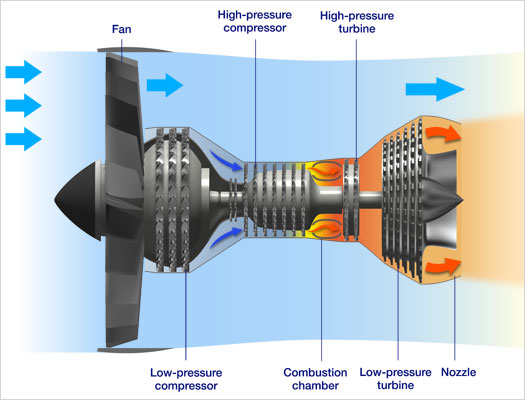
Solution:
One IPLEX videoscope can cover various demands for aircraft engine inspections by just changing the optical adaptors. The following chart indicates the recommended inspection equipment by engine size and part:
| Engine size | Inspected area | Suitable videoscope | Suitable optical adaptor | Remark |
| Small | Low-pressure compressor blades | IPLEX with 4 mm outer diameter | AT120S/FF | |
| High-pressure compressor blades | AT120S/FF | |||
| Combustion chamber | AT120D/FF | |||
| AT120D/NF | For observation of tiny cracks in a magnified view | |||
| High-pressure turbine blades | AT120S/FF | |||
| Low-pressure turbine blades | AT120S/FF | |||
| Medium | Low-pressure compressor blades | IPLEX with 6 mm outer diameter with a rigid sleeve | AT120D/FF | |
| High-pressure compressor blades | AT80S/FF and AT120S/FF | AT120S/FF with a wide field of view enables to observe the entire blade. | ||
| Combustion chamber | IPLEX with 6 mm outer diameter | AT80D/FF and AT120D/FF | - The entire inspection is available by inserting the scope into a combustion chamber all the way around. - A guide tube with a bend assists the inspections of the fuel injection nozzles and the innner/outer walls. | |
| High-pressure turbine blades | IPLEX with 6 mm outer diameter with a rigid sleeve | AT80D and AT120D types | A rigid sleeve is unnecessary when inserting the scope from the combustion chamber and observing through the gap at the turbine nozzle. | |
| AT120D/NF | For inspection of hair cracks on the leading edges | |||
| Low-pressure turbine blades | AT120D/FF | |||
| Large | - The suitable videoscope and optical adaptors are same as those for the medium-sized engine inspections. - The IPLEX of 8.5 mm outer diameter is recommended when all-round inspections are required due to the risk that the 6mm scope insertion tube may be caught in a gap between the rotor and the stator. | |||
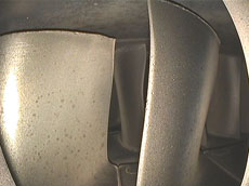
High-Pressure Compressor
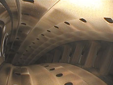
Combustion Chamber
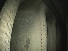
High-Pressure Turbine
(2) Laborious operation to rotate the engine shaft
Challenge:
Operators need to inspect hundreds of blades, which are located at several turbine/compressor stages and mounted on the shaft during the aircraft engine inspection. To conduct the inspection, a collaborative work is required where one operator manually rotates the shaft while another inspects the blade condition. This work not only requires an additional operator for the shaft rotation, but also tends to cause insufficient inspection of the turbine.
Solution:

The engine specific OTT Engine Turning Tools can automatically rotate the shaft with high-pressure compressor/turbine blades at a preferred speed, enabling an inspector to accurately and thoroughly conduct both the shaft rotating and blade inspection operations without the need for a second person.
(3) Time-consuming inspection analysis and report generation
Challenge:
Throughout the inspection, recording a large number of blade images is often the case for inspection analysis and report generation, but within this environment, images are very similar each other and it is sometimes impossible to identify blade types by reviewing images. Thus, many operators experience difficulty and frustration when attempting to find and sort intended images from a large volume of very similar images.
Solution:
Our Inspection Assist Software enables an inspector to record images while categorizing them by inspected stage and putting diagnosis onto the images by way of standardized comment.
After the inspection, the inspector/reporter can efficiently analyze the recorded images and immediately create a report, just by selecting desired images with one-click operation.
Key Benefits with Olympus
(1) IPLEX videoscopes optimized for aircraft engine inspections
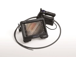
- Bright, high-resolution images faithfully and clearly reproduce very small defects within a gas turbine for accurate analysis.
- The insertion tube with well-tuned stiffness and flexibility, and often TaperedFlex technology, facilitates insert-ability for smooth all-round inspections of the shroud and combustion chamber. It is also exceptionally resilient and can withstand repeated use against sharp blades and other metal surfaces.
- TrueFeel articulation provides exceptional control and precision to improve work efficiency.
- Stereo Measurement technology is suitable for defect measurement on engine blades located in narrow and hard-to-approach areas.
(2) Optimal observation view for various turbine stages
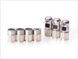
In aircraft engine inspections, demands for observation are different depending on inspected parts and locations. Demands range from wide viewing perspective being required to inspect a combustion chamber to the observation of high-pressure turbines and compressors, which are conducted in narrow spaces where a scope tip of an endoscope cannot be bent. Olympus IPLEX tip adaptors provide full lensing systems with some of the shortest tip lengths in the industry. From near focus, to far focus; direct view to side view and varying angles of view, Olympus’ comprehensive range of optical tip adaptors covers the diverse inspection demands within this environment.
(3) Systems to support efficient and accurate inspections
Olympus provides effective systems to increase your work efficiency of aircraft engine inspections. The OTT Engine Turning Tools allow an inspector to conduct inspections of high-pressure compressor/turbine blades single handedly. The InHelp Inspection Assist Software streamlines all aspects of the inspections and significantly reduces the time for post-inspection work.
In the aerospace industry, many structural components such as wing panels and radomes are made with fiberglass and advanced composites that need accurate thickness control. Composites are often stronger than conventional materials and weigh less. Advanced composites are often made by combining graphite or carbon fibers with epoxy, polyamide, or polyimide resins.
Instant, nondestructive thickness measurements can be made on parts such as wings, fuselage, ducts, panels, and fan blades. Ultrasonic thickness gaging can be done during fabrication or after installation to ensure correct wall thickness.
NOTE: The inherent nature of composite materials can produce varying degrees of anisotropy and therefore sound velocity variation. Care should be taken when evaluating any specific composite application that the sound velocity is sufficiently uniform to permit the required measurement accuracy.
Equipment: Both ultrasonic thickness gages and the Magna-Mike Hall Effect thickness gage can be used for composite thickness measurement.
In general, thickness of most composite materials for aerospace applications in the range of 0.050 in. to 0.750 in. (1.25 to 20 mm) can be measured with the hand-held Model 38DL PLUS or Model 45MG with Single Element Software gages and a selected transducer, commonly an M106 2.25 MHz contact transducer. Certain composites that are very scattering or that are thicker than approximately 0.750 in. (20 mm) may require gages with the HP (high penetration) software option and a lower frequency transducer. In especially challenging cases, waveform display monitoring is recommended to permit on-site operator adjustment of setup parameters.To measure the wall thickness on composite products thinner than 0.125 in. (3 mm), delay line transducers such as the M202 may also be recommended.
If there is access to both sides of the test piece for a probe and a target ball, as in a manufacturing environment, the Magna-Mike 8600 Hall Effect thickness gage can also be used. The Magna-Mike offers the advantage of couplant-free measurements that are independent of sound velocity variations, and with an appropriate probe and targets it can measure up to a maximum thickness of 1.00 in. (25.4 mm).
Ελ. Βενιζέλου 7 & Δελφών, 14452 Μεταμόρφωση, Αθήνα, Ελλάδα |