|
 |
|
Έρευνα & Ανάπτυξη
Οι προηγμένοι μη καταστροφικοί έλεγχοι, έχουν δώσει τα απαραίτητα εργαλεία στην ερευνητική και πανεπιστημιακή κοινότητα ώστε να μπορεί να αναλύει και να εξηγεί φαινόμενα που μέχρι πριν λίγα χρόνια δεν θα μπορούσαμε να αντιληφθούμε.
Μερικά παραδείγματα εφαρμογών Μ.Κ.Ε. στο τομέα της έρευνας παρουσιάζονται παρακάτω.
Background
Performing high-resolution ultrasonic thickness mapping of complex shapes with changing geometries, such as elbows, is very challenging. To address such applications, Olympus has developed its first flexible ultrasonic phased array probe that is capable of conforming to complex shapes creating new opportunities for more applications.
Problem
To map the thickness of a component, conventional ultrasonic probes must be held perpendicular to the surface at every point of data acquisition. This process is slow and corrosion pits can be missed between acquisition points. Using ultrasonic phased array allows large areas to be rapidly scanned at high-resolution, but standard linear phased array probes are rigid and cannot conform to changes in component geometry. Olympus has developed a solution to this problem with its new flexible ultrasonic phased array probe designed for high-resolution thickness mapping of complex shapes. Potential applications for such probes include the inspection of elbows, bends, nozzles, or any part with variable geometry.
Solution
The new flexible phased array probe was designed and manufactured to have both flexibility and mechanical integrity combined with improved acoustic properties. The probe is constructed of SC 1-3 flexible composite that provides flexibility, acoustic impedance, and scalability.
The flexible ultrasonic phased array probe has the following parameters:
| U8 number | Part number | Frequency (MHz) | Number of elements | Pitch (mm) | Active aperture (mm) | Elevation (mm) |
| Q3300182 | XACT-10036 | 5 | 64 | 1 | 64 | 6 |
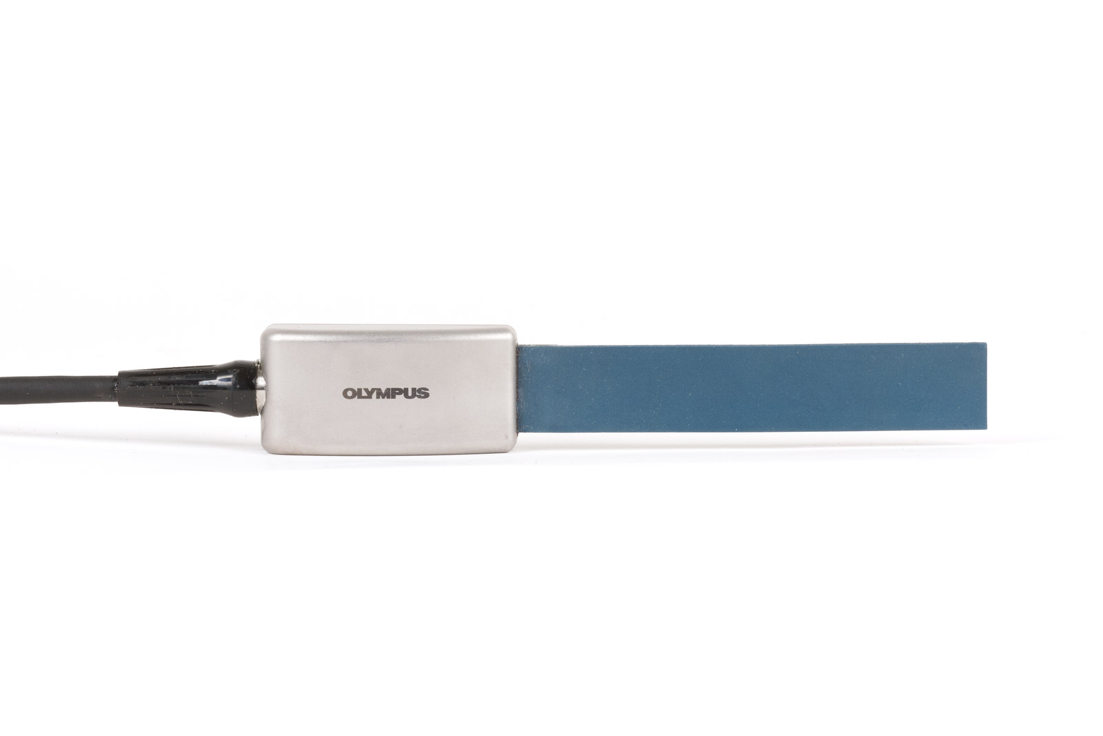
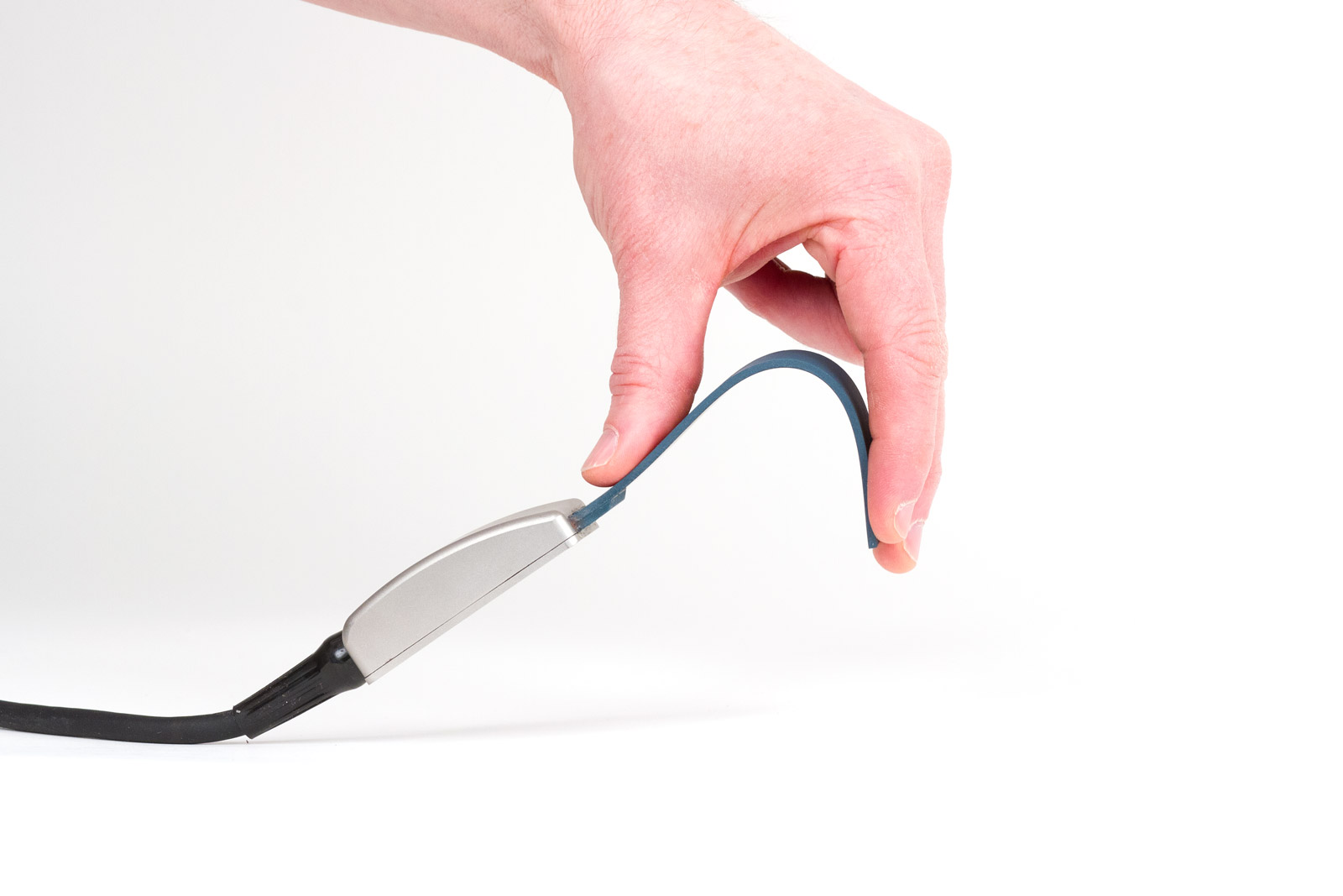
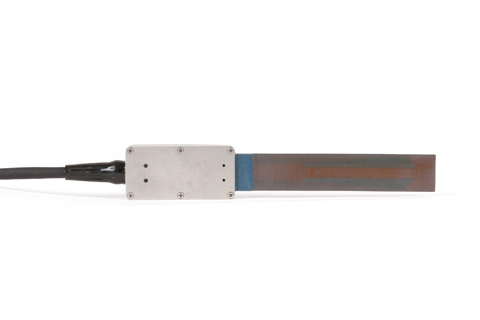
Figure 1: Different views of the Olympus flexible phased array probe.
The mechanical integrity of the probe was tested by flexing it 500 times across a 2-inch radius at 10 cycles per minute. All elements of the probe continued to work perfectly and no damage was observed.
The acoustic properties of the probe were also tested. The flexible probe generated acoustic beams just like any standard phased array probe with the same parameters. The flexible probe exhibited a beam steering of ±30 LW without grating lobes.
The bandwidth of the ultrasonic pulse is around 65% with a center frequency of 5.0 MHz. For corrosion or thickness mapping, this is an acceptable compromise considering the advantages of the probe’s flexibility.
When the probe is in direct contact with a metallic part, the dead-zone is typically 5 mm. When a delay line such as Aqualene is used, the dead zone can be reduced to 2–3 mm.
Results
The flexible phased array probe connected to the OmniScan MX2 was tested on two elbow pipes with evidence of internal corrosion. Focal laws with 4 elements were used, and a 0° LW linear scan over the length of the probe was produced. The resolution of the scan was 1 mm × 1 mm.
The probe was mounted on a flexible delay line made with Aqualene to provide better contact with the part and reduce the dead zone. A layer of polymer gel was mounted on the back of the probe to equally distribute the pressure from the operator (Figure 2). An encoder was attached to this assembly. (Note that the holder assembly is experimental and not yet commercially available).
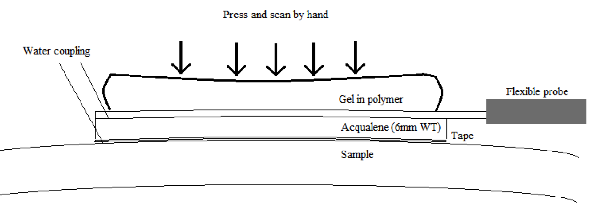

Figure 2: Experimental holder assembly used for testing.
Elbow #1
Elbow #1 had an outside diameter of 170 mm, a wall thickness of 17 mm, and exhibited internal corrosion (Figure 3). The probe scanned along the axis of the pipe as shown in Figure 3.
The surface was covered with a resolution of 1 mm × 1 mm. Small internal corrosion pits are clearly visible in the B-scan and C-scan images (Figure 3). The software displays the position of the pits and enables quick measurement of depth and size.
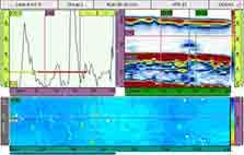
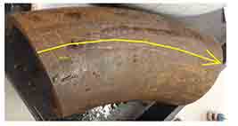
Figure 3: Left: B- and C-scan images of corrosion pits. Right: 170 mm OD elbow.
Elbow #2
Elbow #2 had an outside diameter of 220 mm and a wall thickness of 7 mm (Figure 4). This component has degradation from flow accelerated corrosion (FAC).
The C-scan clearly shows the region of FAC as a growing, gradually corroded area (Figure 4). Red denotes the area of thinner remaining wall while blue shows the area of nominal wall thickness (Figure 4). It is easy to measure both the size of the corroded area and the minimum remaining wall.
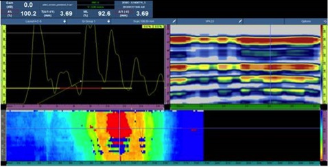
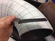
Figure 4: Left: B and C-scan images showing FAC on Elbow #2. Right: 220 mm OD elbow.
These tests demonstrate that the flexible phased array probe is flexible enough to conform to the elbows and that it correctly maps the thicknesses of complex shapes.
Important note
While the flexible ultrasonic phased array probe is useful for complex shape inspection, it should not be considered a heavy-duty tool. You must carefully apply constant pressure on the probe to maintain good signals. Also, the surface of the probe must be protected during the scan. If the probe face is rubbed directly against rough surfaces, it will deteriorate. When used in direct contact with metallic parts, the probe’s surface should be protected with Teflon tape. The use of a flexible delay line is recommended. A holder assembly for the flexible phased array probe is not commercially available at this time.
Considering these limitations, the flexible phased array probe is still very useful when used with proper care.
Conclusion
The flexible phased array probe demonstrates its ability to undertake complex shape inspection on parts such as elbows. It can scan complex components with changing geometries and perform high-resolution thickness mapping.
The flexible probe produces sector and linear scans just like a standard phased array probe.
Note: The flexible PA probe has been designed with specific applications variables in mind. With its current design, this probe is not be suitable for all applications and use cases.

Application
Ultrasonic velocity and attenuation measurements in geological samples such as rocks and minerals.
Background
Ultrasonic sound transmission techniques have been utilized to define the mechanical properties of geological materials. Specifically, these techniques have been used to quantify the physical parameters such as hardness, elastic modulus and grain structure of the material. These techniques have also been used to monitor the compaction of soil or sand under laboratory conditions. These tests can typically be performed on prepared specimens with two flat, parallel surfaces, using through-transmission techniques with low frequency transducers as described below. Field tests are normally performed at seismic frequencies well below the ultrasonic range.
Equipment
Prepared geological samples can typically be tested with ultrasonic flaw detectors such as the Olympus EPOCH 600, or ultrasonic pulser/receivers such as the Olympus Model 5077PR. Pairs of low frequency contact transducers are employed in both longitudinal and shear wave modes. The specific transducers used in a given case will depend on the acoustic properties of the test materials and the sample dimensions, but frequencies of 1 MHz and below are most commonly employed. The frequency should be selected to provide undistorted waveforms in addition to adequate penetration.
Procedure
Samples may be prepared in a variety of shapes and sizes as long as they have two flat, parallel surfaces for transducer coupling. Commonly they will be cylinders or blocks with thicknesses ranging from approximately 2” (50 mm) to 10” (250 mm) in the direction of measurement. Sample diameter or width should be larger than the element size of the transducer being used. Through transmission testing with separate transmitting and receiving transducers is normally employed due to the high level of scattering exhibited by most geological materials at ultrasonic frequencies. Set the instrument’s pulser to through mode and adjust gain and filtering for best response. In through transmission tests, the probe zero delay can be determined by touching the two transducers together and using that signal as the zero point. Gel couplant is useful for longitudinal wave testing to minimize absorption into porous samples. Special high viscosity couplant such as Olympus SWC must be used for coupling shear wave transducers.
Pulse transit time can be measured with either a flaw detector or an oscilloscope or digital waveform display connected to a pulser/receiver. Flaw detector software can also calculate velocity and measure relative signal strength in decibels. The examples below show typical waveforms from two setups.
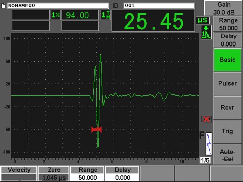
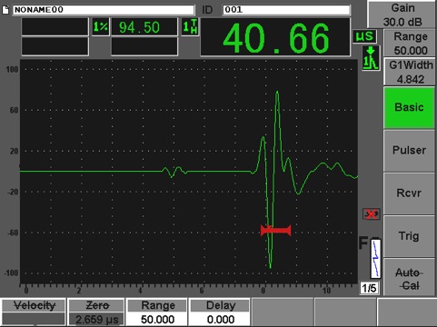
One-way transit time measurement in 3.75” (95 mm) sandstone tested with an Epoch 600 flaw detector, two V102-SB longitudinal wave transducers, and two V152-RB shear wave transducers (both 1 MHz, 1” diameter).
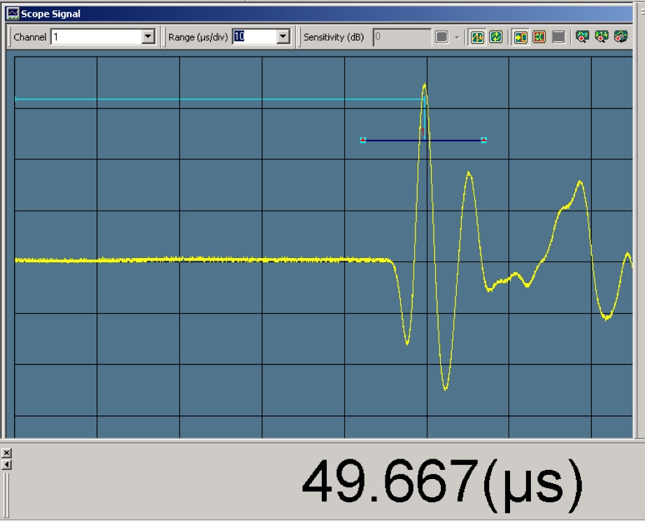
Longitudinal wave one-way transit time measurement in 8” (200 mm) rock salt tested with Model 5077PR pulser/receiver and two V101 transducers (500 KHz, 1” diameter).
The measured velocities along with material density can be used to calculate elastic properties as described in this application note. Attenuation is correlated with physical properties like grain structure or micro-cracking experimentally, using reference samples representing known conditions to establish a calibration curve.
Key Features and Benefits
- Portable and lightweight
- Fits on any lab bench, at the work site, inspection line, production area
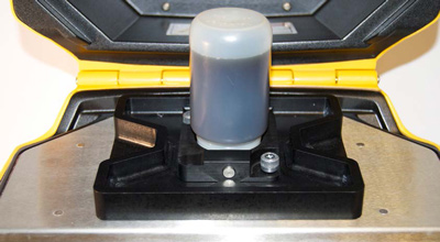
- Sample positioning tray accommodates all sample cups/bottles
- No sample preparation required
- No daily calibrations
- Starts up immediately, results are displayed in seconds
- Closed beam operation for user safety
- Data is stored automatically in tamper-proof format.
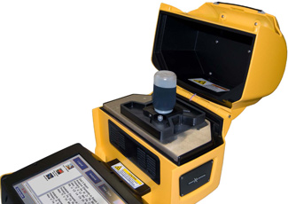
The X-5000 is your answer for the best analytical performance without compromising field portability or operator safety.
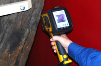
The X-5000 is engineered to be used anywhere - in the field, at the production line, in an inspection area. It ensures operator safety as a fully interlocked, closed beam system. The closed beam, integrated design unique to the X-5000 is a critical safety advancement as portable XRF analyzers continue to increase in x-ray power and be applied to ever more demanding, in-the-field analytical challenges.
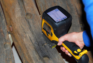
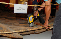
Dr. Raymond Hayes, Underwater Archaeologist, made a major discovery in his investigation of shipwrecks. He found a quick, non-destructive method to analyze them - Handheld XRF. He can now study specimens where he finds them, even when they are moving on platforms off shore, like on boat decks. He no longer has to remove a piece from the wreck and send it off to a lab for analysis. He can simply analyze artifacts on-the-spot without harming them.
Dr. Hayes analyzes wooden shipbuilding materials including oakum, Irish felt, pine tar, caulking cotton, copper sheathing, treenails, and metal fasteners. He studies raw lumber, ship timbers, and various wood treatments for comparative baseline data. Shipwrecks he's studied include the Gunboat Philadelphia, Boca Chica Channel Wreck, USS Scorpion,Cleopatra's Barge or Pride of Hawaii, Charles W Morgan, Indiana, USSTulip, USS Housatonic, CSS Neuse and the CSS Alabama.
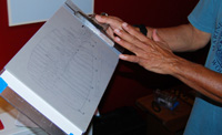
Schematic of Shipwreck Data Points
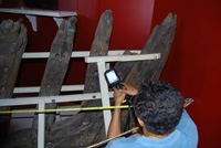
Measuring Tape Guided Analysis
Soil Foot and Board of Balance
Metal Posts and Fasteners
It is unlikely that any metal from the Sparrow-Hawk would have survived over time simply from scavenging. However, the metal post found in the stern and the metal fasteners found where the rudder attached did have different compositions. The post may have been inserted in the 1860's when it was brought from Cape Cod to be exhibited on Boston Common. The fasteners may have been attached around 1890 when it was transported back to Plymouth.
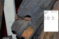
Stern Post
DELTA Camera Shot of Fastener Test
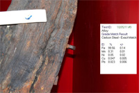
Fasteners Near Rudder Attachment
Olympus Innov-X Research & Discovery Grants
This Applications Brief is based on a 2011 Grant awarded to Dr. Ray Hayes. His work involves the analysis of materials used in current and historic ship-building as well as of marine sediment and seawater as an additional source of elemental chemistry in shipwreck specimens. Shipwrecks he has studied span 200 years and encompass a wide variety of densities and origins. Along with adding to the overall knowledge base, Dr. Hayes research on the Sparrow-Hawk may shed more light on its voyage.
Since 2008, Olympus Innov-X has been sponsoring worldwide research and discovery projects through its Academic Grant Program. The program is flexible in nature in that it supports work in the form of access to analytical equipment, research collaboration, publication, and/or sponsorship at conferences and workshops. If you have a compelling project and are interested in applying for an Olympus Innov-X Grant.
References
1: Cape Cod's Oldest Shipwreck, The Desperate Crossing of the Sparrow-Hawk; Mark C. Wilkins; Copyright © 2011 by Mark C. Wilkins; published by The History Press; Charleston, SC 29403; www.historypress.net.
Ελ. Βενιζέλου 7 & Δελφών, 14452 Μεταμόρφωση, Αθήνα, Ελλάδα |