 |
|
Εξορυκτική Βιομηχανία
Μερικές από τις πιο απαιτητικές εφαρμογές Μ.Κ.Ε. σε πετροχημικές βιομηχανίες παρουσιάζονται παρακάτω.
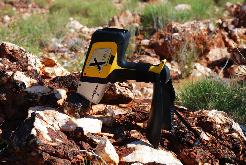
The DELTA couples an ultra high resolution SDD detector with a powerful 4W X-ray tube, delivering the fastest, most precise analysis available today in a handheld X-ray Fluorescence (XRF) analyzer. The introduction of new SDD technology has significantly advanced the application of Field Portable XRF for the Mining & Mineral Exploration Industry.
The key benefits include:
- Significantly increased speed
- Higher count-rates mean shorter testing times
- In-Air Light Element Ability with Xpress Mining Mode for Al, Si, P, Ca, & S
- Lower detection limits (LOD's) and higher precision across the entire periodic table
Unprecedented Performance in Bauxite Ores
LOD's: The 1 Million Dollar Question
The determination of the analytical limit of detection (LOD's) depends on many aspects, not directly related to the instrumentation of choice. Some of these influences include (influential factor denoted in brackets):
- The energy of excitation or X-Ray source (instrument) Note: This is not all about obtaining the maximum voltage (or keV). It is reliant on the process of fine-tuning both the X-Ray voltage and current to maximize the received count rate and therefore analytical precision (instrument).
- The Atomic Number and associated response of element(s) being analyzed (sample).
- Concentration of elements present (sample).
- Relative density & matrix composition (sample).
- Sample size, granularity & surface geometry (sample & user).
- Length of test run (user).
- The quality of the instrument calibration & QC samples used to "tweak" the instrument (user & instrument).

Application: Measuring the depth of textile and steel reinforcements in rubber conveyor belts, and measuring the remaining rubber thickness of in-service belts during maintenance.
Background: A wide variety of rubber conveyor belts for heavy-duty industrial and mining service such as ore and mineral transportation incorporate internal layers of woven fabric or steel cords for strength reinforcement. Conveyor belt manufacturers need to check the depth of the reinforcement layer across the belt in order to insure that the product meets specification. After installation, belt users need to periodically check the thickness of the remaining rubber as the belt wears down in order to estimate the remaining service life before replacement. Because large belts can be very expensive, accurate information on remaining rubber thickness is valuable to users. Our instruments and transducers have been successfully employed in this test for many years.
Sound energy reflects off the first layer of reinforcement, and in the case of textile or fabric reinforced belts very little sound energy will penetrate deeper. Measurement of total belt thickness is normally possible only in the case of some steel-reinforced belts where there is sufficiently wide separation between the steel cords to permit sound energy to travel unobstructed the opposite side of the belt. However, the critical dimension for most users is the amount of rubber over the first reinforcement layer, not total thickness. This is usually a straightforward application for ultrasonic thickness gaging.
Equipment: Conveyor belt rubber thicknesses under approximately 12.5 mm or 0.50 in. can usually be measured with standard thickness gage models38DL PLUS and 45MG with Single Element software. For greater thicknesses, the High Penetration software option for these gages will be needed should be used. Thickness measurements can also be made with any of the EPOCH series flaw detectors. In the case of certain very large belts, with rubber thicknesses approaching 50 mm or 2 in., the Epoch series flaw detectors are the preferred instruments.
The transducer selection will depend on the range of rubber thickness to be measured. For rubber layers between approximately 1 mm (0.040 in.) and 6.25 mm (0.250 in.), a 2.25 MHz delay line transducer (M207-RB) will usually be recommended. For measurement of rubber between approximately 2.5 mm (0.100 in.) and 25 mm (1 in.), a 2.25 MHz high penetration contact transducer (M1036) is commonly used. Other transducers are available for thinner and thicker rubber layers.
As with any application involving attenuating materials, use of gel couplant or glycerin (Couplant B) is recommended in preference to less viscous fluids. In the case of severely worn in-service belts, any loose rubber or other debris should be removed from the surface before testing.
Procedure: In the most common situation, using the M1036 transducer to measure the outer rubber layers on belts with textile or fabric reinforcement, start with the gage's M1036 default setup and increase maximum gain as necessary to measure the thickness range of interest. If necessary for measurement of thin belts, increase initial gain as well. In any of these setups, gain may usually be increased up to the point where the gage displays a constant false reading when the transducer is uncoupled, which indicates that gain is too high. 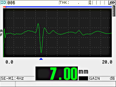
Typical conveyor belt measurement with M1036
To measure thin rubber layers over textile or fabric reinforcement with the M207 delay line transducer, use the M207 Mode 2 default setup and adjust gain and blanking as necessary based on the echoes from a reference standard. 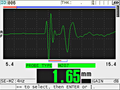
Typical thin rubber layer measurement with M207
Measurement of depth of braided steel cord reinforcements can be more challenging because their irregular contour presents a less optimum reflecting surface. Careful adjustment of instrument gain with the aid of a reference sample is recommended. Also note that echo polarity will be positive rather than negative because the steel represents a high impedance reflector. 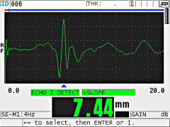
Steel cord depth measurement with M1036
Sound velocity in rubber compounds will typically be on the order of 1.650 mm/uS or 0.0650 in/uS. The Olympus Applications Lab is always available to assist with gage setups for specific transducers and belt types.
Gear-Tooth Surface Inspections
 Gears are a critical component of the equipment used in the mining industry. From processing equipment to heavy equipment, all of these gears must be closely monitored for surface-breaking cracks caused by stress during operation. If these anomalies are not found during inspection, it can lead to catastrophic equipment failure.
To perform any gear inspection, the equipment must be brought to a complete standstill. To keep maintenance costs low and reduce the impact on operations, these stoppages need to be kept as short as possible in order to get the equipment back in service quickly. Gear failure while in-service is unacceptable; the costs of replacement due to such a failure are very high, mainly because of the time that the equipment is out of service. There are several types of equipment with gear components used in mining facilities, so maintaining them is a big job. Any effective gear-tooth maintenance program needs to have a reliable and efficient surface inspection method.
Maintenance managers want an overall evaluation of the gear’s condition; pinpointing any cracking is important, but the surface condition is also a major concern. Magnetic particle inspection (MPI) is currently the most common NDT method used for gear-tooth surface inspection. However, prior to performing an MPI inspection, extensive preparation is necessary. First, the gears must be cleaned of their lubricant, which is very gummy grease that is particularly difficult to remove.
Advantages of Eddy Current Array over the Standard Surface Inspection Methods:
Using eddy current array technology for gear-tooth inspection helps keep the surface preparation to a minimum, as the gears only need to be lightly cleaned. Performing an inspection with ECA is also very fast. The acquisition speed can reach up to two meters per second and only one pass is required to scan one full side of a gear tooth. The instrument calibration is very simple; all that is required is a material sample with target defect to ensure that the sensitivity is adjusted properly. Setup files can be saved and easily recalled for subsequent jobs. The data recording utility permits post-process analysis, as well as data archiving, and reports can be easily created, directly from the instrument.
- Major time savings when compared with the traditional NDT method.
- Intuitive imaging, very similar to MPI and PT representations.
- Result traceability and post-process analysis.
- One-step inspection, high scan speed, and instant results.
- Defect depth evaluation capability.
- Adjustable sensitivity.
- Environment-friendly method (no chemicals involved).
Equipment used
Olympus ECA solution – OmniScan MX with ECA module
- C-scan view.
- Battery operated.
- Drives up to 32 channels and up to 64 channels with an external multiplexer.
- Encoded or time-based scan.
- Data and setup recording.
Olympus ECA solution – MS5800 Instrument
- PC-based instrument.
- C-scan and 3D C-scan view.
- Drives up to 64 channels.
- Encoded or time-based scan.
- Data and setup recording.
ECA solution – Probes
- Robust ECA probe specially designed for gear-tooth inspection.
- Transmit-receive probe design for better results.
- Absolute mode signal for easy interpretation.
- One probe covers a range of different tooth sizes.
- Two probes are usually enough to cover all tooth sizes.
- Encoder can be attached if needed.
- Customized probes can also be developed.
Replacement of Traditional NDT methods with ECA
Eddy current array can easily replace traditional NDT methods such as MPI and PT for surface inspection. ECA imaging provides similar imaging to the traditional techniques but with more possibilities. Rejection criteria can be adjusted so that it is based on probe sensitivity, a feature that is unavailable with the traditional methods.
A Variety of Familiar Color-Palette Choices Offering More Possibilities
The MXE 3.0 ECA software features a range of patented color-palette representations that replicate the look of traditional NDT methods and facilitate the intuitive display of ECA signals.
Example of sensitivity adjustment that can be done using ECA method.
Powerful 10 Watt, Optimized Mobile XRF for REE Exploration.
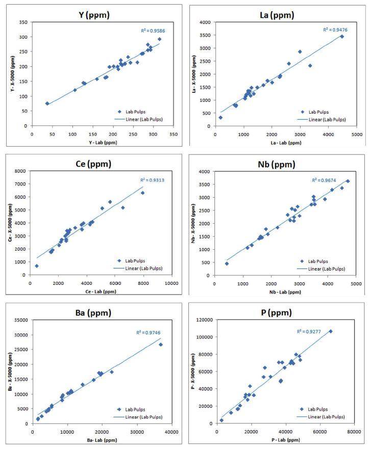
The X-5000 Mobile X-Ray Fluorescence (XRF) Analyzer sets the benchmark for Power and Portability. Utilizing a full 10 Watt, 50kV X-ray tube, coupled with a Large Area Silicon Drift Detector, the X-5000 is the most powerful field portable XRF available on the market. This makes it well suited to Rare Earth Element (REE) Exploration & Mining applications, as higher excitation enables direct analysis of the Light REE's (La, Ce, Pr, Nd, Pm & Sm), together with important Pathfinder's such as Y, Ba, Nb, Ta & Zr and exceptional Light Element performance on Mg, AI, Si, P, S, K & Ca. This is all achieved utilizing the X-5000's multiple analytical Modes and 6-position primary beam filters.

In addition to outstanding performance, the X-5000 is delivered in a light weight, highly visible, field rugged design with full safety interlocks and no radioactive isotopes, using miniaturized X-ray tubes. This combined with a powerful inbuilt PC (running Windows XP Embedded) and a large industrial grade colour touch-screen gives you full control of your analytical needs at the touch of a button.
X-5000 - 60sec Test in 3-Beam Soil Mode
Ελ. Βενιζέλου 7 & Δελφών, 14452 Μεταμόρφωση, Αθήνα, Ελλάδα |

