|
 |
|
Ναυτιλία
Ο μεγαλύτερος όγκος εμπορευμάτων και καυσίμων παγκοσμίως μεταφέρεται με ειδικά σχεδιασμένα πλοία μέσω θαλάσσιων οδών. Η ανάγκη για όλο και μεγαλύτερα πλοία αλλά και η διατήρηση του ήδη υπάρχοντος στόλου, οδήγησε στην ανάπτυξη ειδικών μη καταστροφικών ελέγχων, με σκοπό την πρόληψη ατυχημάτων με τεράστιες οικονομικές και περιβαλλοντολογικές συνέπειες. Μερικές από τις πιο απαιτητικές εφαρμογές Μ.Κ.Ε. στην ναυτιλία παρουσιάζονται παρακάτω.
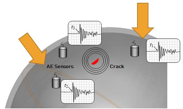
Application: Detection of fatigue cracks in marine propellers using Eddy Current testing.
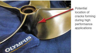
Background: Propellers used on boats of all sizes and types undergo cyclic fatigue. Cracks occur as a result of cyclic fatigue causing potentially serious consequences including total loss of water craft, loss of lives or delay in time of arrival. Inspection of propellers is applicable across the maritime industry. Many different types of materials are used for propellers including bronze, aluminum, stainless steel and carbon steel, all of which are susceptible to cyclic fatigue. Cracks can originate at many locations on propellers. In most cases the crack begins at points of highest stress loads associated with stress risers such as sharp edges, thick to thin transitions and areas of where weld repair has occurred. The most common point of failure on propellers is where the blade joins to the hub. Cracks occur anywhere along the axis of the blade to hub radius.
The advantages of eddy current testing in this application are as follows:
- In many cases, especially in large ocean going vessels, inspection of the propeller in-situ is a big advantage. Eddy current testing can be performed under water while many of the other NDT is very difficult or impossible.
- Eddy current can be used on all the aforementioned materials of construction. In some cases where propellers are coated the inspection could possibly be conducted without removal of the coating.
- Eddy current can be used to detect anomalies slightly subsurface such as casting imperfections.
- Depth of anomalies can be estimated in some cases.
- Can be performed underwater.
- In the case of larger propellers, Eddy Current Array testing (ECA) can speed inspection and also provide a permanent record.
Applicable NDT techniques are subject to material of construction, type of defect to be detected and location of subject being inspected. Magnetic particle inspection, dye penetrant and visual inspection may also be used where applicable.
Equipment:
Nortec 600 eddy current flaw detector
Pencil Probe, 100-500 KHZ, part number 9222164
Right Angle Weld Probe, 100-600 KHz, part number WCD90I-5-50
As with most NDT techniques, a reference standard with known flaws should be constructed for calibration and performance verification.
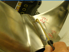
Procedure: In order to achieve optimum results, two scans using two different eddy current probes were used to complete the inspection. The first scan used a conventional pencil probe, a common probe used in detecting surface cracking. The second scan was performed using a Nortec Weld probe, chosen due to its contoured face.
For each probe two scans were made and an image captured for each corresponding scan. One scan was made across the entire area of interest while the other scan was made directly across the reference notch to simulate the response from a surface breaking defect. A scan from a smaller reference notch on a separate standard was also done with each probe for comparison purposes.
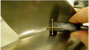
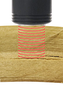
Example of scanning a propeller with eddy current
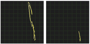
Comparison of crack signal to defect-free area using weld probe
Finger tip probe can be used as well.
Critical to protect precision equipment operating under extreme temperatures and heavy loads, top quality lubricants depend on specially formulated blends of organo-metallic additives. These additives extend lubricant life, protect metal surfaces and increase the range in which a lubricant can be used. Additive elements such as calcium and zinc contribute to key lubrication characteristics; sulfur and phosphorus key to extreme pressure lubricants. A sound maintenance program that routinely measures metals in the lubricating oils not only reduces the expense of routinely dismantling the components for visual inspection, but can indicate and identify the worn component before that component fails.
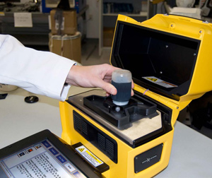
The X-5000 X-ray Fluorescence (XRF) analyzer provides a quick, simple way to ensure your lubricants and fuels are in the best possible condition prior to use and your heavy equipment is maintained properly. It is critically important to protect your equipment operating under extreme temperatures and heavy loads. The X-5000 allows for instant analysis, providing vital information at that precise moment and not weeks later.
Wear Metals
A sound maintenance program that routinely measures metals in the lubricating oils not only reduces the expense of routinely dismantling the components for visual inspection, but can indicate and identify the worn component before that component fails. The X-5000 analyzes wear metals such as Cu, Fe, Ni and V in oils and lubricants. When the levels of these metals change, it allows you to do predictive maintenance and identify small problems before they become costly failures.
Lubricants/Additives
Top quality lubricants depend on specially formulated blends of organo-metallic additives. These additives extend lubricant life, protect metal surfaces and increase the range in which a lubricant can be used. The X-5000 measures additive elements such as Ca and Zn for improved lubrication and S and P for extreme pressure lubricants.
By monitoring these levels, you know the status of your lubricant and when to add more of the additives.
The X-5000 sets the benchmark for Performance, Power and Portability. No sample preparation, just collect it and analyze – right on the spot.
Key Features and Benefits
- No sample preparation required
- No daily calibrations
- Portable and lightweight
- Starts up immediately, results are displayed in seconds
- Fits on any lab bench, at the work site, inspection line, production area
- Closed beam operation for user safety
- Sample positioning tray accommodates all sample cups/bottles
- Data is stored automatically in tamperproof format

The X-5000 is engineered to be used anywhere – in the field, at the production line, in an inspection area. The X-5000 is your answer for the best analytical performance without compromising field portability or operator safety.
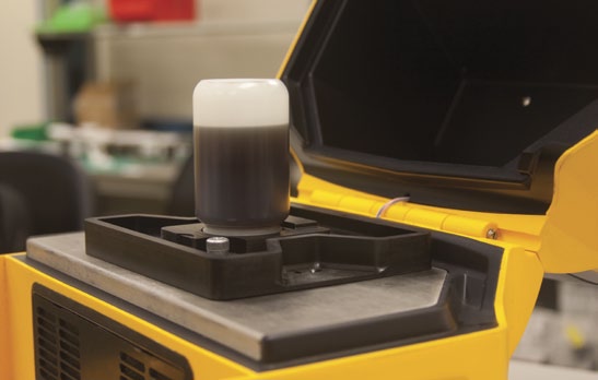
Zero Sample Preparation
Simply put the oil in a sample cup, use the sample tray to ensure proper alignment and press “Start.” It’s that simple to get accurate analysis every time.
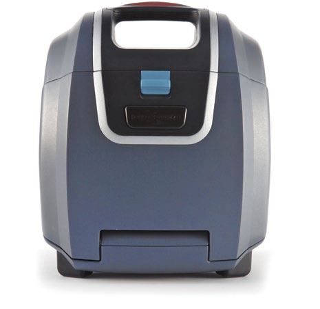
Rugged and Portable
The X-5000 is packaged into an easy to carry, 22 lb. battery operated XRF with integrated PC and industrialized large touch screen can be set up in almost any environment within minutes.
Stable Calibration
There is no need to recalibrate the unit frequently. Just a 15 second calibration check daily and you will know your answers are accurate down to the ppm level for a wide range of elements.
Closed Beam
The X-5000 has a closed beam, interlocked design. This means that you can have a high power analyzer while making sure that your operators are always safe.
Application
Detection of laminar cracking in fiberglass structures, tanks, pipes, boat hulls, wind power blades, and similar applications.
Background
Because of its laminar layup structure, fiberglass is potentially subject to cracking parallel to the surface, either because of applied stresses or weaknesses resulting from manufacturing anomalies. These hidden internal cracks can have a significant impact on structural integrity and are normally not detectable by radiography or NDT techniques other than ultrasonics.
Ultrasonic flaw detection offers a simple method for locating internal voids. High frequency sound waves coupled into the part by a small probe called a transducer will reflect from cracks and voids in a predictable way. Ultrasonic waves will travel through a material until they encounter a boundary such as a far wall, but if there is a crack within the sound path that will generate an additional echo where there should not be one. By observing echo patterns on a display screen, a trained operator can quickly and reliably verify material integrity.
Equipment
Any of the Epoch series flaw detectors can be used for this test, including the EPOCH 600, EPOCH 1000, EPOCH 650, and EPOCH LTC. The type of transducer used in a given test will depend on the specific part geometry and thickness. The specialized M2008 delay line transducer (0.5 MHz, 1” diameter), designed for optimum performance on thick fiberglass and composites, is normally recommended for thicknesses greater than approximately 12.5 mm or 0.5”. For thinner fiberglass, the M1036 contact transducer (2.25 MHz, 0.5” diameter) is commonly used.
Procedure
Ultrasonic flaw detection is a comparative process in which the echo pattern generated by a good part is compared with the echo pattern from a test piece. Since sound waves will reflect from voids or cracks, changes in the echo pattern indicate changes in the internal structure of a part. In testing fiberglass, the operator typically looks for the presence of echoes within a marked gate or window that represents the interior of the test piece. While the inhomogeneous nature of fiberglass frequently generates scatter noise reflections even from solid material, cracks whose area approaches the diameter of the sound beam typically return strong localized indications that will be recognized by a trained operator.
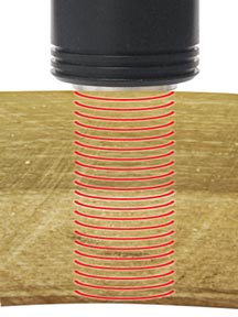
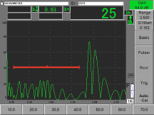
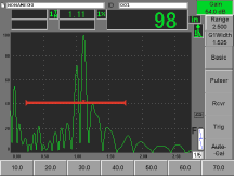
The example below shows detection of a large laminar crack void in a 50 mm (2”) thick fiberglass tank wall, using a Epoch 600 flaw detector and a 500 KHz transducer. The transducer is coupled to the top of the part. With a good part, the sound travels to the bottom surface and creates a reflection from a depth of 2”. That is the peak at the right side of the image in the waveform below the picture at left. But when a crack is present, the sound will reflect from the crack and create a peak within the zone on the screen that is marked with the red gate, representing the middle of the part. The presence of a strong echo in that area indicates a large discontinuity in the part. The inspection takes only a few seconds per test point.
ASTM D4294
With federal and international regulations becoming increasingly stringent, the need to determine the sulfur content in the characterization of petroleum oils and fuels is a critical component. Energy Dispersive X-Ray Fluorescence, EDXRF, is a well established technique for the analysis
of sulfur in petroleum products. The analysis requirements are regulated thru the international standards such as ASTM D-4294.
To meet these tough requirements for the measurement and control of sulfur in fuels and other petroleum products, Olympus has developed the X-5000. The X-5000 is also ideal for measuring other elements, like Fe, Ni, V, Pb, Cr, Cu, and Cl in crude oil, as well as other heavy and refined petroleum products.
The analytical performance, closed beam safety and ease of use of traditional bench top XRF units are all captured in the X-5000. And it delivers true field portability, being packaged into an easy to carry, 22 lb. battery operated XRF with integrated PC and industrialized large touch screen.
The X-5000 sets the benchmark for Performance, Power and Portability - No sample preparation, just collect it and analyze - right on the spot.
Key Features and Benefits
- Portable and lightweight
- Fits on any lab bench, at the work site, inspection line, production area
- Sample positioning tray accommodates all sample cups/bottles
- No sample preparation required
- No daily calibrations
- Starts up immediately, results are displayed in seconds
- Closed beam operation for user safety
- Data is stored automatically in tamper-proof format
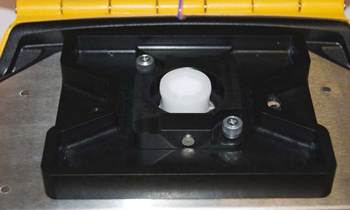
The unique sample tray ensures proper placement of the sample every time for accurate analysis. The sample tray accommodates both bottles and cups of any size.
No sample preparation, no daily calibration.
The X-5000 is engineered to be used anywhere - in the field, at the production line, in an inspection area. It ensures operator safety as a fully interlocked, closed beam system. The closed beam, integrated design unique to the X-5000 is a critical safety advancement as portable XRF analyzers continue to increase in x-ray power and be applied to ever more demanding, in-the-field analytical challenges. The X-5000 is your answer for the best analytical performance without compromising field portability or operator safety.
Ελ. Βενιζέλου 7 & Δελφών, 14452 Μεταμόρφωση, Αθήνα, Ελλάδα |