|
 |
|
Διυλιστήρια
Στις εγκαταστάσεις άντλησης και διύλισης πετρελαίου λαμβάνουν χώρα μια σειρά από προηγμένους μη καταστροφικούς ελέγχους. Οι έλεγχοι αυτοί πραγματοποιούνται για την ορθή αξιολόγηση του εξοπλισμού των μονάδων με σκοπό την πρόληψη όχι μόνο ενός σοβαρού ατυχήματος, με καταστροφικές συνέπειες για τους ανθρώπους και το περιβάλλον αλλά και για την αποφυγή διαρροής παραγόμενου υλικού με οικονομικές συνέπειες. Οι βιομηχανικές εγκαταστάσεις αυτού του τύπου αποτελούνται κυρίως από αγωγούς, δεξαμενές, αντιδραστήρες και εναλλάκτες θερμότητας διαφόρων τύπων.
Μερικές από τις πιο απαιτητικές εφαρμογές Μ.Κ.Ε. σε εγκαταστάσεις άντλησης και διύλισης πετρελαίου παρουσιάζονται παρακάτω.
The DELTA Takes Detection Limits of Chromium (Cr) in Carbon Steel to an All Time Low!
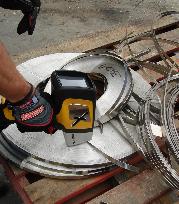
It has been shown that small amounts of Cr in carbon steel pipes significantly reduce the rate of flow accelerated corrosion. Consequently, highly accurate measurements of low levels of Cr in carbon steel are critical for predicting the end of life in these pipes. In general, Cr is present in carbon steels as a residual tramp element ranging from 0 to 0.25%. The critical level of Cr monitored for FAC prediction is at about 0.04% (400ppm). The DELTA Premium, the latest development in HHXRF, goes to an all time high in accuracy and an all time low in detection limits for Cr and other metals. It detects trace levels of Cr as low as 0.004% (40ppm) in alloys; and 0.01% (100ppm) in carbon steel for FAC inspections. Although HHXRF is a non-destructive technique, accurate low Cr analysis of in-service and oxidized pipes can require some sample preparation to remove surface material before measurements. Portable angle grinders with alumina grinder disks are recommended.
Comparison of DELTA Premium Handheld XRF with Certified Assays of Trace Cr in Carbon Steel
| Standard | Certified %Cr | HHXRF Measured %Cr | HHXRF %Cr +/- |
| IARM 229A | 0.015 | 0.015 | 0.002 |
| IARM 28E | 0.079 | 0.080 | 0.005 |
| IARM 33D | 0.139 | 0.139 | 0.006 |
| IARM 35F | 1.160 | 1.210 | 0.006 |
DELTA Premium Analysis Time: 120sec Beam 1; 30 sec Beam 2
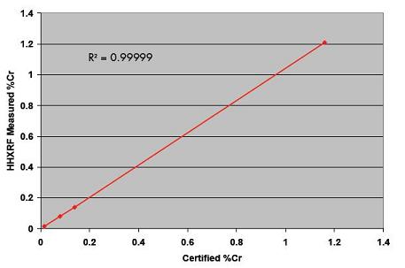
Excellent Accuracy and Low Levels of Detection are Critical for Predicting Accelerated Corrosion
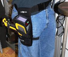
In addition to testing for flow accelerated corrosion, the power supply industry depends on HHXRF analyzers for startups, shutdowns, general maintenance, and trouble shooting. Managers cannot afford to depend on out-of-date and unreliable equipment, or untimely support of equipment. They also cannot afford to fall behind the technology curve. The analytical capabilities of HHXRF continue expanding, and new features continually enable operators to be more effective and efficient. Upgrade your HHXRF to the DELTA - the latest HHXRF loaded with innovative features and backed by the industry's best service and support.
Handheld XRF for Metals & Alloys Industries
| Iron & Steel | Non-ferrous | Scrap & Secondary |
Iron and steel are the most widely used of metals and alloys. Lighter metals, non-ferrous, newly developed and exotic alloys are also utilized extensively, but iron and steel are considered the basic raw materials for the majority of industrial goods and construction. Although produced from ores mined around the globe, steel is one of the most recycled materials in the world. From base form to recycled materials to finished products, metals and alloys are integral to the fabric of society, the consumption of which is often considered a primary indicator of development and economic progress. | ||
Metals Alloys is a serious, dynamic business.
The DELTA XRF analyzer is an essential tool for all businesses involved in the trade or use of metals alloys. In seconds, you can nondestructively measure 25+ elements. Turnings, shavings, rods, wires, small parts, components, sizeable materials and large structures can all be analyzed directly, non-destructively. How you get them, how you make them, how you use them, how you sell them is how you measure them. Whether you check purity, chemistry, or grade ID for highest value, maximum recovery, quality, conformance, or maintenance and safety, our DELTA XRF analyzer will give you immediate answers to take action on now.
Summary
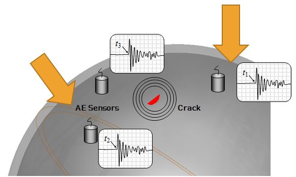
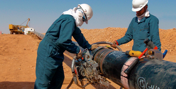
The Girth Welds used to connect pipe across country or offshore for the transportation of petroleum must be inspected during construction to ensure safe operation. In order to prevent inspection from bottlenecking the construction process, the inspection method must be rapid, repeatable and meet applicable code requirements. By using fully automatic zone discrimination systems deployed on and offshore, Phased Array ultrasound is increasingly used to meet this need.
Introduction
The most common volumetric inspection methods for newly constructed pipeline are radiography and ultrasonic testing. In many cases the ultrasonic method is preferred due to its inherent lack of hazards for those working around the inspection site, the immediate availability of test results, and the ability to precisely size defects especially in the through wall plane. Pipeline weld joints often have very narrow bevel angles making traditional pulse echo inspection difficult as lack of fusion on the bevel face would reflect the sound at an angle such that it is never received back to the probe for detection.
Typical Advantages of Ultrasound/Phased Array vs. Radiography:
- High probability of detection (POD) especially for cracks and lack of fusion
- Accurate sizing of defects height and less repair using Engineers Critical Assessment
- No radiation, hazard, or additional licensing
- No screened off areas, work can go on around AUT
- No chemical or waste material
- Real-time analysis for instant evaluation and feedback to welder
- Setup and inspection reports in electronic format
Solution
The PipeWIZARD inspection system is a phased array based fully automatic inspection system for pipeline girth welds. It usually consists of phased array and Time of Flight Diffraction (Tofd) probes to provide rapid full volumetric inspection of these welds. The main components include an acquisition unit and motor controller, a computer, and the scanner. The instrumentation is sealed and ruggedized to withstand the often harsh conditions of the areas where pipelines are installed.
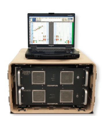
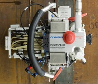
PipeWIZARD acquisition unit and motor controller box with computer and Scanner on band
Background
CRA-clad pipes are increasingly used for the transport of hot and corrosive materials because of the higher resistance to corrosion provided by the corrosion resistant alloys (CRA) used for the pipe cladding. However, the layer of protection that these alloys provide also impedes effective ultrasonic inspection of dissimilar girth welds in the piping. The industry has been searching for a simple and reliable solution to this particular challenge.
Problematic
Ultrasonic inspection of dissimilar girth welds in CRA-clad piping poses a particular challenge. As the material of the clad layer (Inconel, stainless steel, etc.) differs from that of the parent material (carbon steel), the quality of the interface between these materials makes the rebound on the internal wall (ID) of the pipe unpredictable or even impossible. In addition, the anisotropic structure of the cladding and the weld creates ultrasonic mode conversion and different beam orientations. Consequently, high-precision techniques like zone discrimination cannot be used. Pulse-echo using the second leg of the ultrasonic beam is impossible, which makes inspection of the cap and its subsurface extremely challenging.

Profile of a dissimilar girth weld of a CRA-clad pipe
Solution
Olympus has developed a dual matrix array (DMA) probe with the goal of increasing the capacity for detection and sizing of flaws that are located at the root, in the volume, and on the surface of dissimilar welds of large-diameter clad pipe. (For more details about dual matrix array, please consult the application note: Dual matrix array for the inspection of acoustically noisy welds.)
The tests discussed in this application note were performed on a 36-inch pipe sample, using a 2.25 MHz DMA probe composed of 2 matrices of 28 elements (7 x 4) mounted on a 55-degree LW wedge.

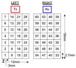
On the left: picture of the DMA probe; on the right: schematic of element distribution
A portable phased array instrument, the OmniScan MX2 32:128 PR, was programmed to assure full coverage of the weld without skipping off the internal wall of the pipe. Two different groups were used:
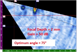
- Group 1 with a sector scan from 30 to 76 LW focused at 2 mm deep to provide coverage of the upper volume of the weld and the surface
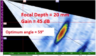
- Group 2 with a sector scan from 30 to 76 LW focused at 20 mm deep to provide coverage of the root and the volume of the weld
The picture below shows the modeling of the beams generated at the interface between the 2 matrices.
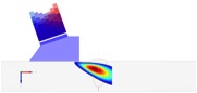
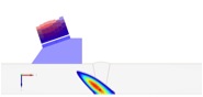
Beam modeling representation: (on the left) 75 LW beam focusing at 2 mm [part of group 1 ]; (on the right) 45 LW beam focusing at 20 mm [part of group 2]
The inspection was done manually without the use of a scanner or an encoding device.
Equipment
The following equipment was used for the inspection:
1 dual matrix array probe:
1 flat wedge:
Software:
2.25DM7X4PM-19X12-A17-P-2.5-OM: (U8331715)
SA17-DN55L0-IHC (U8831948)
SetupBuilder Software 1.0R5
TomoView (optional)
The set of reference defects for the mock-up is shown below. They include: 2.5 mm side-drilled holes located in the center of the weld at T/4, T/2, and 3T/4, as well as 10 mm long and 2 mm deep surface notches located at the toe position, at the top of the weld, and at the root.

Schematic of the reference defects of the clad-pipe mock-up
Results
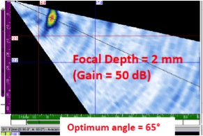
All SDHs were detected with a SNR superior to 45 dB. The SDHs located at 3T/4 and T/2 were detected with group 2 focusing at 20 mm, and the SDH located at T/4 was detected with group 1 focusing at 2 mm.
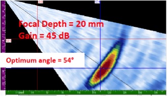
Detection of the SDH: 3T/4 on the left; T/2 in the center; T/4 on the right
The toe notch located on the same side of the probe and the notch located at the top of the weld were detected with a SNR superior to 40 dB and by focusing group 1 at 2 mm (as shown below). The notch located at the root was easily detected with group 2 focusing at 20 mm; however, the picture was not recorded.
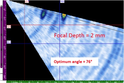
Detection of notch located at: (on the left) toe position; (on the right) at the top in the center of the weld
Important to Note
The results presented in this application note concern the use of a 2.25 MHz DMA probe on large-diameter clad pipe. The results that are discussed in this application note cannot be transferred to smaller diameter pipe. Olympus is currently working on developing specific solutions and inspection strategies for these diameters.
Also, this inspection was done manually without a scanner or an encoder. While this technique is flexible, it is also operator dependent. Therefore, these results cannot be transferred as is to a high-production-rate environment. Olympus is also in the process of developing solutions for this type of environment with the use of similar tools.
Conclusions
A 2.25 MHz DMA probe paired with the OmniScan MX2 32:128 PR can be advantageous for the inspection of clad pipe with large diameters. Full coverage of the dissimilar weld was ensured. SDHs located in the volume and notches located on the ID and OD can be detected using an inspection scenario of two groups steering the beams from 30 to 76 LW, focusing at 2 and 25 mm.
These results are very promising, and Olympus is intent on further developing this strategy to extend the use of these tools to smaller clad-pipe diameters and high-production-rate environments.
Background
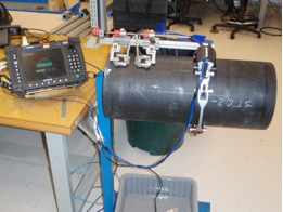
High-density polyethylene (HDPE) piping has been used in place of steels in the petrochemical, power, and mining industries due to its exceptional resistance to corrosion and erosion. Recently, HDPE has also been used for nuclear safety-related cooling water applications. The application of nuclear quality assurance requirements requires reasonable assurance that the production fusion joint is sound. Ultrasonic time-of-flight-diffraction (TOFD) inspection of fusion joints is an easily employed nondestructive examination tool that can be used to provide additional assurance of fusion-joint integrity.
Problem
The HDPE joint process is typically subject to the following flaws: lack-of-fusion, cold fusion (partial bond), inclusions (embedded), and voids. There is currently no consensus in the industry as to the nature and size of rejectable flaws; however, nondestructive examination is often requested to detect these conditions.
HDPE material has some specific characteristics that make its inspection difficult. Its acoustic impedance and sound velocity is similar to the materials commonly used in ultrasound wedges, which makes it difficult to achieve appropriate refraction of sound at the interface. In addition, coupling between the Rexolite wedges and the material can be difficult to achieve. Also, HDPE material is very attenuative as compared with metals, which often prohibits the use of higher ultrasonic frequencies. It also exhibits a natural high-frequency filtering effect. To overcome these hurdles, low-frequency probes mounted on TOFD Water Wedges are used.

Equipment
The following equipment is used for the inspection:
- OmniScan TOFD capable unit
- Panametrics C542-SM or C546-SM Centrascan (6.25 mm or 0.246 in. element dia.; 2.25 MHz and 3.5 MHz frequencies)
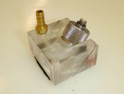
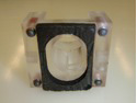
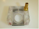
- TOFD (ST1) 60L Water Wedges
- 1 CHAIN scanner Semi-automatic Scanner
- 1 CFU-03 or comparable water delivery system
Optional Equipment
- Panametrics Preamplifier Model 5682 (500 kHz-30 MHz/30 dB)
Typical procedure
A conventional TOFD procedure is used for the inspection of HDPE, with the following specifications:
- The probe centering spacing (PCS) is adjusted to provide beam cross at 66% of the thickness. Additional configurations are recommended on thick-wall pipes to improve detection near the OD or ID surfaces.
- The probe assembly is mounted on the Chain scanner.
- Electronic gain on the OmniScan is adjusted to set the lateral wave (LW) signal at 60%.
- The CHAIN scanner is mounted on the pipe, and the inspection is performed in one rotation.
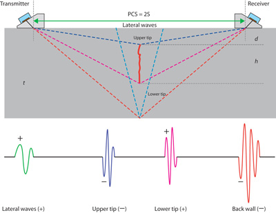
Time-of-flight diffraction pattern of butt-fusion joint HDPE
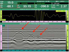
Results
The screen capture below, with A-scan and circumferential B-scan images, shows the results on a 25 mm (1 in.) thick HDPE sample with ID calibration cuts ranging in depth from 11.6 mm (0.456 in.) to 2.9 mm (0.114 in.). The three inserted cuts are detected clearly with a good signal-to-noise ratio.
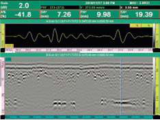
The following screen capture clearly shows the presence of voids and/or contaminants in the16 mm (0.629 in.) -thick HDPE butt-joint of a 150 mm (5.9 in.) diameter pipe.
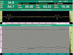
This image is indicative of a poor bonding condition at the inner wall through almost the entire diameter of a 54-mm (2.125 in.) -thick HDPE butt-joint of a 450 mm (17.716 in.) diameter pipe.
Conclusion
Use of TOFD in conjunction with the OmniScan and other appropriate tools has shown to be a valid method for nondestructive inspection of HDPE butt-fusion joints. While the nuclear industry continues to evolve with respect to detecting rejectable flaws, further studies and trials continue with the use of ultrasound phased array.
Ελ. Βενιζέλου 7 & Δελφών, 14452 Μεταμόρφωση, Αθήνα, Ελλάδα |